Something like that. Perhaps the black and white colour could be switched around (so there’s a black interior line) with a very dark background and a white (or user colored outer line).
The interior line thing is not a good idea. Whenever you want to fit a thing in precisely, you have to rely on lines that are as narrow as possible, but still recognizable. But the middle line effectively turns a single line into 3 lines, so how are you going to achieve precision? That becomes impossible.
Michelist
you make 2 lines one after the other, one with 1px width and another with 3px width behind and you get the effect of 3 lines but sure I am not a fan of the idea.
I also think that the inner line is not a good idea, it can cause more problems for others than benefit.
In the past few days I have been sorting out other expectations for the “assistant tool”, some of them are optimization suggestions, some are feature requests. And made some predictions about them:
1.Rectangle and ellipse tools are affected by linear perspective ruler.
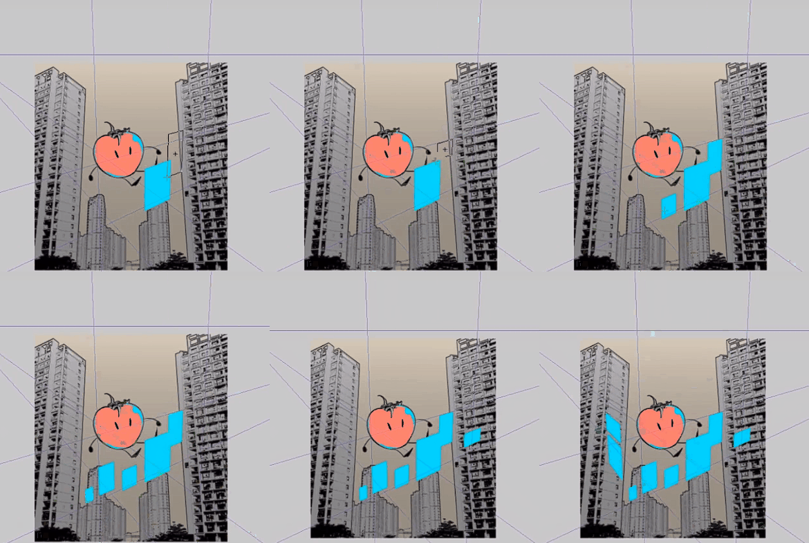
GIF images are from CSP. This simplifies the workflow of “drawing four strokes + filling color” and greatly improves the work efficiency.
But I predict that this is not a simple thing, and it is even possible to rewrite the code on a large scale…
2.Unnatural leap question
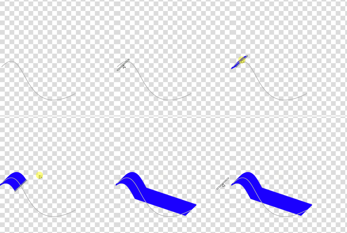
This is not a very urgent request and will not appear in slow painting. But I think it would be better to be optimized.
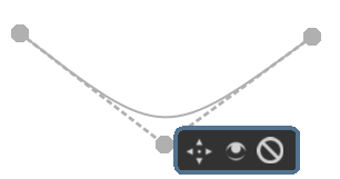
3.”easy mode“ for ”spline“
”Spline “is currently a cubic Bezier curve. In” easy mode ", it becomes a quadratic Bezier curve. It allows users to click less when creating and editing.The difficulty should not be high.
4.Binding of control points of multiple rulers
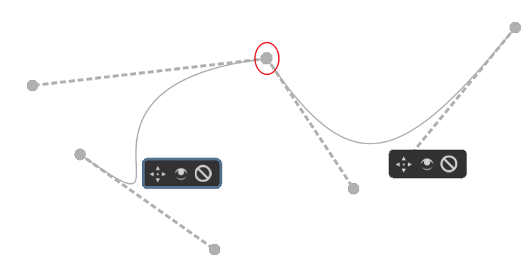
After being bound, you can drag and adjust multiple rulers at a time. This allows us to better edit complex shapes.
It should be a more difficult job. There are also some possible alternatives, such as directly creating a multi segment polyline.
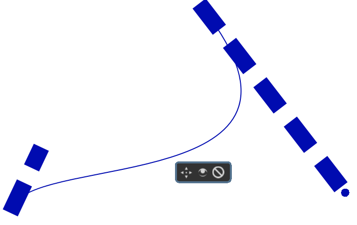
5.After zooming in, the control point of spline ruler is too small
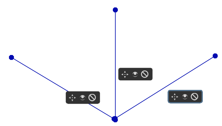
- Isometric perspective ruler
Currently, we need to create three “parallel rulers” to achieve this effect. And the angle on both sides is not easy to control.
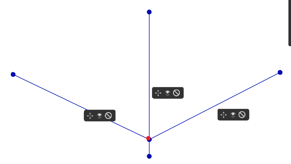
So, we need a shortcut method. I think it’s roughly the following shape:
Or do some advanced design: since the vertical angle is basically unchanged, we add a control point on it. This red control point can only be moved on a vertical line, and can manipulate the angle of both sides at the same time.This is more friendly to Android users.
7.radial lines ruler
Referring to lazynezumi, based on the “vanshing point”, remove the perspective-related controller and add a control point for adjusting the radian.
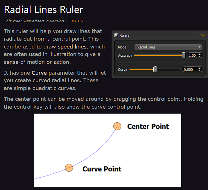
From the name, it is also more recognizable to newbies.
I also think it’s possible to add more control points to manipulate the arc.
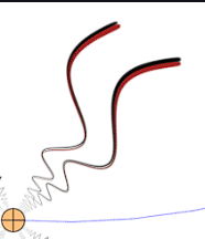
(The picture is of lazynezumi’s script, I think adding control points to achieve a similar effect is feasible)
It can be used with multibrush to create patterns. The multibrush is more regular in angle and the radial lines ruler is more regular in shape.
the last one could actually be a good idea for a brush.
Yes to all but the last one (which I wouldn’t need for my work). Rectangles and circles with perspective would be sooo good.
This is already done  And will be available in Krita 5.1 (already available in Krita Next).
Thanks for the post! (Also please next time someone ping me -.- since I didn’t know this thread had more answers).
There is Perspective Ellipse assistant coming in Krita 5.1, looks like this:

and I accidentally confirmed that it works with quickly creating shapes (though you’d need to first set up the assistant…):

if you use “t) Shapes Fill” brush.
In 5.1, it won’t work with Perspective Sensor yet, especially since I still have some issues:

and I plan many more features for it, like moving towards 1st, 2nd or 3rd vanishing points, scaling it up or down etc. (but it requires quite some math, and it won’t happen before 5.1).
I also have plans to make Line Tool work with perspective. I haven’t thought about other tools deeply, but I can add it to my TODO, though no promises. However that rectangular thingies would be useful… though I think it is more likely that a Polygon tool would work with those assistants much better than Rectangle Tool. Would that still be fine with you?
I know what you mean, and I know why it happens: it’s because currently every point under the cursor is mapped to a closest point on a curve. And with specific shapes and specific movements it happens that either the cursor points are too far in between, and end up like this, or even they are very often (with slow painting), but there is never a point where the closest point on the curve is a point on that valley (in your example). So the painting engine gets several points before the valley and then the next point is suddenly after the valley, and the engine just makes a straight line between them, since it doesn’t really know about assistants or anything.
I’m not sure yet how to fix that…
I feel like a multi-segment polyline would be a better approach, personally. Even technically it would be easier.
I even talked to Dmitry recently and he said it would be better if Perspective grids that you grow from Perspective grid’s side handles were one assistant, too.
It looks more like the control lines to those points are drawn incorrectly and hence too big. Handles always have the same size, no matter the zoom level.
Maybe. Though I don’t agree with limiting it to just a few types of isometric; if it’s a new assistant, it should be fairly versatile. See here: Painting with Assistants — Krita Manual 5.2.0 documentation
I’m not sure I understand what that means.
In Blender you can adjust the angle of the isometric grid as an assistant property. But what if this new assistant were to be an axonometric grid?
Axonometric projection - Wikipedia
Not sure it should be a priority though (I actually prefer to see some QOL improvements to the existing toolset). 

No, I belive the ellipse that is drawn in correct, I’m pretty sure of it. I can tell you how I achieve it, in case you find any issue (Dmitry was also not sure at first but then admitted that it must be right). I think the small difference you see on the bottom might be just because of calculations precision issues when drawing (plus you can’t really use Width/2 if that’s what w/2 means, because this is 2 point perspective, not 1 point perspective (the second point is just not visible here, it works like Perspective grid, and I haven’t tried to keep horizontal lines perfectly horizontal), so there is a high chance the division on the bottom line is not perfectly 50-50).
How I got the ellipse: (please note: I know it’s complicated, but there is very little straight-forward formulas for generic ellipses on the internet, so often I had to find it myself or go the long way to get something 100% correct)
- I get the perspective QTransform that translates the original square into the final tetragon, which also means it transforms the original circle into the ellipse. This part is easy because it’s implemented in Qt. However, I cannot really use it that much because (1) transformation is perspective based, and (2) I can only get the ellipse by taking a point from a circle and transforming…
- I take five points from the original circle and transform them. That gives me five correct points on the final ellipse.
- I use those five points to get the generic formula of the final ellipse. (The formula is
ax^2 + bxy + cy^2 + dx + ey + f = 0, but because of some constraints I can divide everything bya, so there are only five coefficients to calculate, which I can do by solving a linear system with matrix calculations → using Eigen, of course, not calculating it myself). - Thanks to the formula I can calculate the center of the ellipse, the “first” axis angle to 0X axis, and then with some more calculations, finally the axis points (vertices).
- I can use the axis angle and the axis lengths to use a more standard Ellipse mechanisms to draw it and project cursor points; it means I have the Ellipse with a transformation that is no longer perspective, but just rotation and translation (move).
I had made tests to make sure all of those parts do calculate correctly. It took me like four weeks, all in all  Even though the foundation was already done by our SOK student, Srirupa Datta (Add Perspective Ellipse Assistant Tool (!1343) · Merge requests · Graphics / Krita · GitLab) (but then the issue was that it wasn’t working correctly, so the calculations are all mine now, I think).
Also the axis that is drawn inside the ellipses are the actual ellipses axis, while the horizontal line you drew and the other line are the axis of the initial circle. I was already asked to maybe draw the original ones too since they will be useful for artists to see. I’m still wondering what to do - both seem useful, but they can’t be both drawn, it would be too many lines in one place, I think.
I was a long while ago but i did technical drawing by hand on paper. I do not know the formulas but I can draw perspective without any programs aid if I really want too and how things should look like.
Circles are wonky but they respect rules also. Circles are width == height on the bounding box, but when it is not the case they are Elipses width != height. None the less the bounding box around both Circles and Elipses have the same rule, on where they touch it, on width/2 and on height/2. You can easily see the circles internal vertical line does not match the perspective end point. if you correct that the other section (lower left) will tilt to the right spot.
Even if you create an eccentric ellipse where the geometric center does not match the bounding box center all lines will converge to the perspective end point just the same.

what I am seeing is an ellipse being contained by a square and not really being projected to the perspective.
Distance in perspective is a challenge.
The bottom picture in @EyeOdin’s suggestion takes distance into account. It moves towards 3d I guess.
Also, the red and green lines in lazynezumi’s fisheye perspective are simply resulting perspective axises pointing to the cursor(x, y, and z axises). Now when you trace towards a direction, the software intuitively snaps the cursor to the matching axis. Just like in the case of Krita’s perspective drawing tools in general, or when you set three vanishing points.
Lazy Nezumi however takes things a little further by printing distance units on the axis, helping estimate distance in 3d space when at least 3 vanishing points are set or when you use LNP’s fisheye perspective tool. Krita already brought an update taking calculation of distance in perspective with the new 2 point perspective tool.
The source code of the module might help you with what you’re doing with the ellipse in perspective.
Basically, we’re just asking to make the center of the ellipse to also fit in the perspective, distance taken into account.
But you see, it doesn’t need to. It’s an axis of the final ellipse (not the places where they touch the tetragon!), when you re-transform it to the original circle, it won’t be the vertical axis, so it isn’t parallel to the left and right side of the tetragon, so it doesn’t go to the vanishing point. It would only be true if the trapezoid I drew was a perfect symmetrical trapeze. But it isn’t, because it’s skewed, because I drew it fast just as a demonstration.
Here is a perfect symmetrical trapeze:

And for a more visual explanation, why it doesn’t need to go to the vanishing point:

This shows the same circle with Perspective grid on it, and as a bonus, an actual circle that I transformed using a Perspective Transformation tool:


The fact that axis after the transformation are no longer axis of the final ellipse was one of the reason for how painful all those calculations were (Btw I haven’t tried using Transform Tool to confirm my calculations before; so I’m glad to see that it does match )
Does it help to understand why I believe it’s correct? Does it look more correct now?
I see now that I will have to change the way it is drawn, if it brings confusion. I will probably add the touching points instead of axis. I thought axis are natural since they are in the other Ellipse Assistant, but if they cause harm and no benefits, there is no reason to keep them.
But it is. The center of the final ellipse is not the center of the circle in Perspective. Those are two different points. I just don’t draw the other one. But I will, since the current state seems to cause confusion. I will update this thread with new screenshots when I do this.

Because the axes of the final ellipse are not the same as axes of the original circle in perspective. I see how that might be confusing, I will make sure those axes won’t appear in 5.1.
I thought they would be useful if someone would be using this assistant to just draw an ellipse in a rectangle etc., since the Ellipse Assistant is in some circumstances a bit wonky to use, but since the perspective is the main purpose, and it seems confusing, and it’s just decoration (it doesn’t affect the ellipse in any way), I will just remove it and maybe draw the original axes in perspective.
I am not in favor or against. I just thought it was the contact points to the bounding box. since it is not to me it is neutral. if the circle has a good projection it has a good projection.
This:
is correct:

If you were to draw that traditionally, the first thing you have to do is to find the center of the square in perspective that is the quadrilateral. Then you make 2 lines that go through the center each to a vanishing point. You are cutting the square in 4 smaller, equal, squares, but in perspective. Where those lines cross the quadrilateral is where the ellipse (a circle inscribed on the square, but in perspective) should touch the sides.
In the image: the red lines are there to find the center of the square; the blue lines are the lines that cut the square in 4 equal smaller squares. The yellow lines are there just because the second vanishing point is too far away, so I just found the center of the 2 rectangles with them, and used the centers to draw the horizontal blue line (since it must pass also through those), instead of the second vanishing point.
That the vertical blue line meets with the minor axis of the ellipse at the bottom is just a coincidence.
Here:
you cannot just cut a line that goes to a vanishing point in half, you have to take into account foreshortening.