This proposal emerges from a previous thread, discussing how to draw square and cubes in perspectives with krita. After many contributions and long discussions, this previous thread leads to the necessity of a formal feature proposal.
The main idea is to revisit the current “perspective” assistant tool and to propose a new user interface for it. Most of its code development could reuse existing materials and this proposition could be interpreted as an evolution of the krita assistant tools. A short and clear summary of the geometrical construction of 1-point perspective could be found in the following 12’ very nice video:
- Beth Harris and Steven Zucker, How one-point linear perspective works (video),
Khan Academy
For reading the present proposal, very few mathematics are required, only 2D basic geometric operations, such as line intersections. Moreover, there is absolutely no 3D concepts. Here, 3D effects are created in the human brain, no more. Let us turn to the proposed user interface. We identified two stages for creating a “1-point perspective” assistant tool, plus and optional third stage for its customization. Next, the proposal studies a possible interface variant and a combination of this tool with the transform tool. It closes with a short discussion and future works.
1.1] Step 1: vanishing point and horizon line
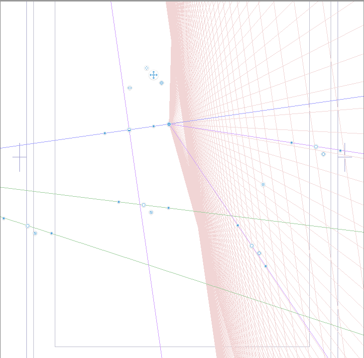
During this stage, the user has to provide three points, freely chosen anywhere in the bi-dimensional plane, and denoted by VP, A1 and A2. By convention, we assume that A1 has a lower abscissa than A2 (i.e. A1 is at the left of A2). The first user’s click defines VP, the vanishing point. Then, when the cursor moves, a line from VP to the cursor position appears. At the second click, we get either A1 or A2, depending upon the future position of A2.

Without loss of generality, and for simplicity, assume that the user chooses A1 for the present explanations. After the second click, a set of lines, appear, starting from VP, and equi-distributed between A1 and A2, which is defined by the cursor position. There are N+1 of such lines and N is a strictly positive integer that could be customized in the “tool option” panel. The default value for N is 8. Simultaneously, a line, passing by VP and parallel to the line (A1,A2), appears: this is the horizon line. Note that the horizon line is not necessarily horizontal: you could think about a boat on the sea. Note also that this interface differs from the already existing “vanishing point” assistant tool: the points here are equi-distributed along the segment [A1,A2] while the present assistant tool bases upon a equi-distribution of angles around the vanishing point, similar to sunbeams. This difference is here of major importance. At the third user’s click, the cursor position freezes the location of A2.
1.2] Step 2: tiles and depth reduction
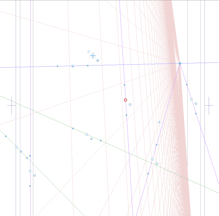
Here comes the major contribution of this proposal. During stage 2, the user has to provide an additional line, parallel to (A1,A2), and that intersect the two segments [VP,A1] and [VP,A2] at B1 and B2, respectively. The two intersections B1 and B2 express as:
    B1 = VP + theta*vector(VP,A1)
    B2 = VP + theta*vector(VP,A2)
where theta is a real number. Observe that theta belongs in the open interval ]0,1[ if and only if the cursor position belongs inside the banded region delimited by the horizon line and the line (A1,A2). This is a major assumption for continuing the computations.
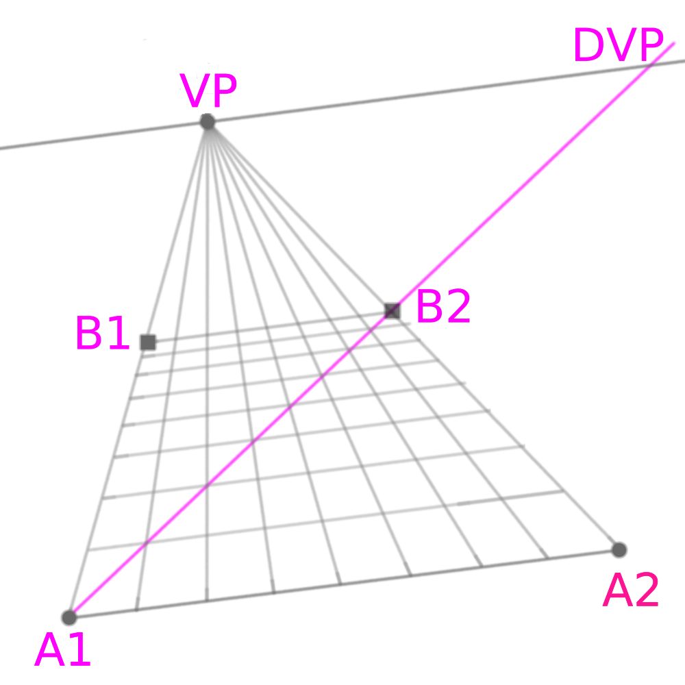
On the previous image, the annotations in magenta do not appear to the user’s during the interface: only the grey lines should be shown. These annotations are shown here for the purpose of the geometrical construction. First, let us consider the diagonal line (A1,B2). It intersects the horizon line at DVP, the diagonal vanishing point. It also intersect the N+1 lines coming from VP and going to the equi-distributed points in the segment [A1,A2]. We then obtain N+1 intersection points along the diagonal segment [A1,B2]. Next, we draw N+1 segments passing from these intersection points and parallel to (A1,A2): we obtain the tile together with the size reduction. During the cursor displacements, the tile are dynamically updated, as a preview, and when the user clicks, the composition is frozen. After that, the value of theta could be modified by using the square-shaped handles at B1 or B2. Optionally, we could also consider another equivalent handle at DVP, for convenience.
Observe that the cases theta=0 and theta=1 correspond to a degeneracy: the “diagonal line” is no more diagonal and the intersections are no more well-defined. For a practical implementation, we first compute a guess, denoted as theta’, by using the previous formula. We then bound strictly this guess value in the interval ]0,1[ as:
theta = min(0.99, max(0.01, theta'))
By this way, the cursor could go anywhere in the bi-dimensional plane, and theta is initialized as theta=0.5. When the cursor is outside the banded region, the value of theta remains unchanged.
1.3] More goodies: walls, ceiling, back and front
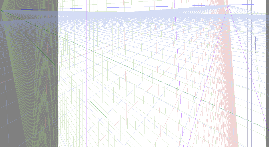
At this stage, the tiles are well defined: the user could still adjust the position of VP, A1, A2 and B1 or B2, by using the handles. In addition to the number N of tile density, the “tool option” panel provides five independent boolean flags for showing the left and right walls, the celing, the front and the back. In the 1-point perspective, the front and the back are in frontal views, and do not present any size reduction: the tile have just to fit along the [A1,A2] and [B1,B2] segments.
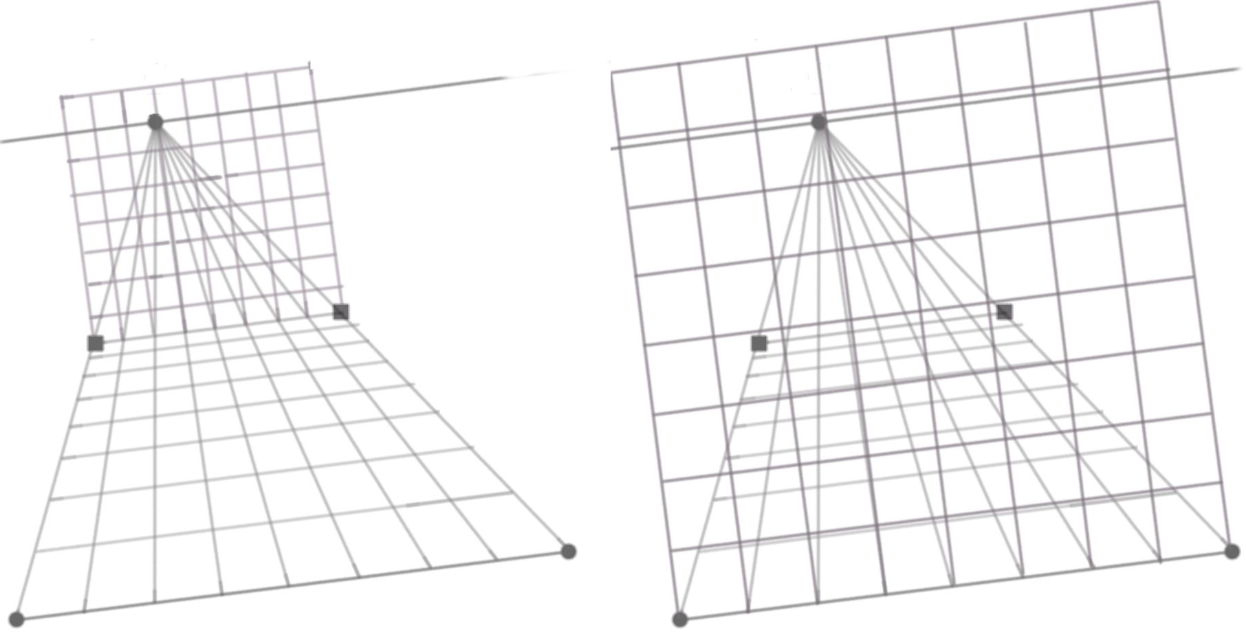
Next, the left and right wall are elaborated: the tiles also have to fit along the boundaries with the floor, back and front walls. Finally, the ceiling could be added in the same way.

The “tool option” panel could looks like:
  number of tiles: 8
  show floor     : [x]
       ceiling   : [ ]
       left wall : [ ]
       right wall: [ ]
       back      : [ ]
       front     : [ ]
Finally, when drawing with a brush, a “snap to assistant” boolean flag appears in the tool option panel:
[x] snap to assistant
1.4] Alternative definition based on the first tile
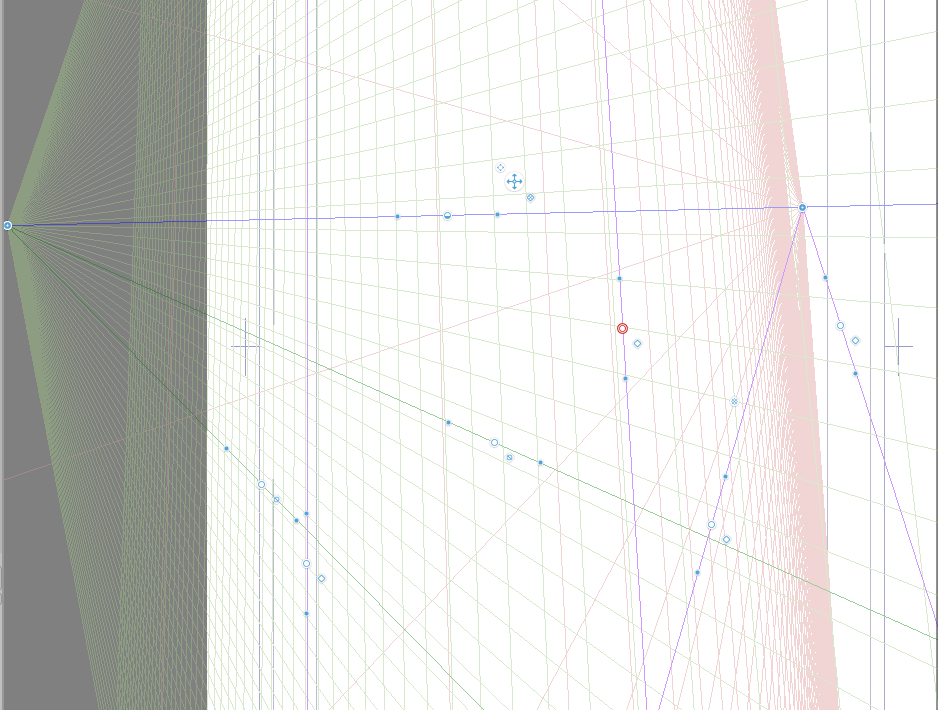
The previous user’s interface could be called the Rubik’s cube one, since it is convenient for drawing such a composition, or similarly a scene in a room. Another popular composition is the railway one, or similarly, the tree-lined road. This new interface solves in an elegant way the railway problem, as presented in the krita manual. In that case, it is more convenient to define instead, at step 2, the theta coefficient via the depth of the first tile. Now, the two handle are located at B1’ and B2’, as shown on the figure:
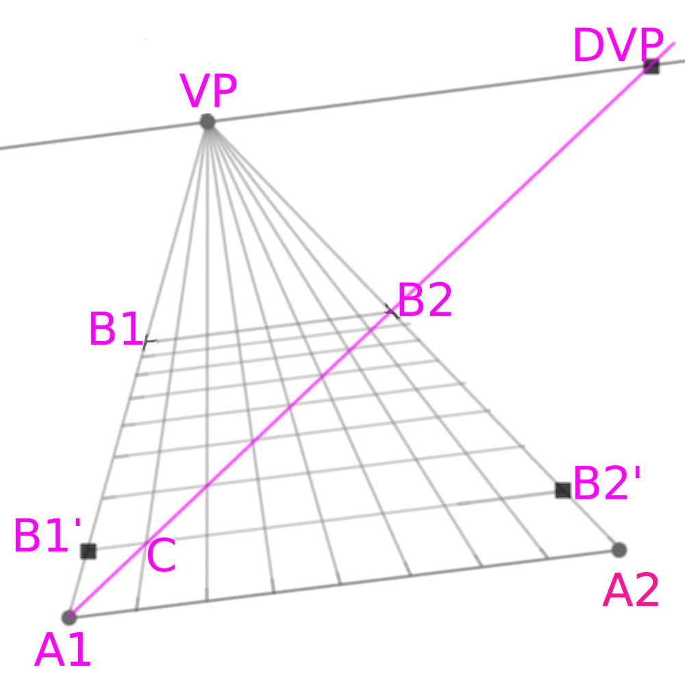
The intersection of the line passing via the cursor and parallel to (A1,A2) intersects the two segments [VP,A1] and [VP, A2] at B1’ and B2’, respectively. It also intersects the segment between VP and the first equi-spaced point between A1 and A2 at a point C. Then, the diagonal is the line (A1,C) and finally, B1, B2 and the theta coefficient are obtained as in the previous case. Note that, by increasing the value of N, the number of tiles by sides, the B1 and B2 points go closer to VP: this is convenient for a strait railway or tree-lined road.
The “tool option” panel could have an additional scrolling menu:
  tile adjustment: at last tile (default)
                   at first tile
1.5] Combining with the transform tool
Tiles are convenient as guides for placing some patterns. Patterns can be placed thanks to the “transform” tool combined with its “perspective” option.
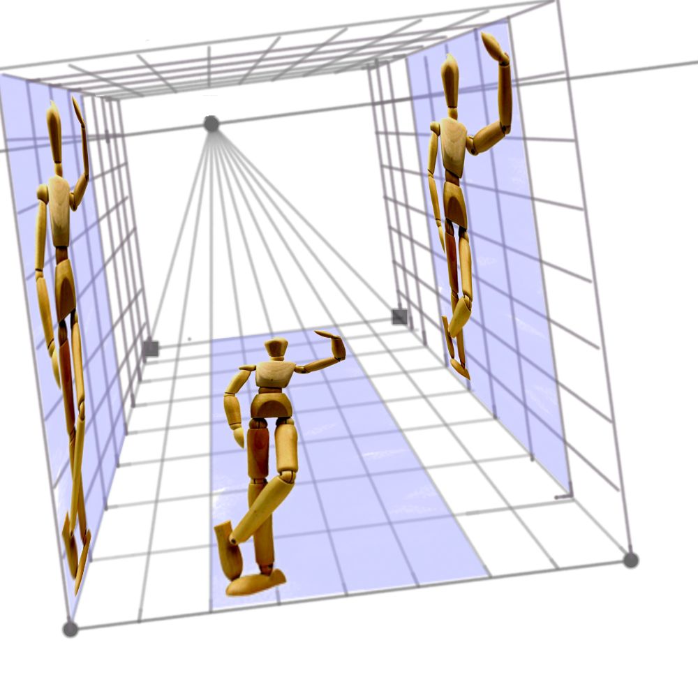
The previous image was produced by using three clone layers of this photography of my wood mannequin, together with a transformation mask. The aspect ratio of the original mannequin image was 1:2. Observe how the tiles are used as guides for a careful placement that conserves this aspect ratio. Note also that, for the two clones staying in a vertical position, the positions of the eyes are chosen close to the horizon line.
Discussion and conclusion
Krita already provides some closely related assistant tools:
- the “perspective” tool: see e.g. https://www.youtube.com/watch?v=shGV4sH8xbw starting at 4’12’’
- the “vanishing point” tool combined with a “parallel ruler”, see e.g. https://www.youtube.com/watch?v=LN_JGs5o-bc
While they are useful for maintaining the user’s brush along some directions, none of these tools address the fundamental problems in perspective:
- reducing lengths in depth
- reporting lengths from one direction to the other
The current proposal is an attempt to fill this gap, at least for 1-point perspective. In the future, if krita’s users and developers are interested by, I will prepare a proposal for a “2-point perspective” tool (i.e. for oblique perspective). Such a perspective is very common in practice, about 50% of the compositions involving perspective. I will also consider its possible extension to 3-point perspective (i.e. panoramic views) and nonlinear (fisheyes, etc) cases.
As a final remark, I anticipate some classical questions:
- Why not using blender and then importing in krita ?
→ Blender is 3D, suitable for complex scenes, see e.g. this, while I consider here only classical 2D scenes with an evolution of the krita assistant tools: 3D effects will be created in the human brain. - Do you known if photoshop already has something similar ?
→ I don’t use photoshop, I cannot answer this.
 There are some really good and well-reasoned suggestions here.