"Close gap" in Fill tool

For reference, Jehan who made the GIMP one, wrote a long blog post about his research on the topic. I tested only early version of the feature, but it was slower than colorize-mask afair.

I totally agree: Colorize mask is slow (especially on comic pages) and not flexible (yes, elaborate preparation: you have to draw color markers immediately on the canvas and it’s difficult to tweak their color in the process). I also adopted Colorize Mask because the GMIC plugin had a long period of being buggy with multilayer output so I had no other choices. The G’MIC Smart Coloring Filter is a good method, but it was a bit frustrating I had to perform many small click on mini island of colors at that time on comic pages. A real game of point and click to fusion the areas. Maybe I should revisit it on my modern workflow now @Deif_Lou made the fill tool able to fill continuously while pressed down. (I just tested it: indeed, very quick and usable with a stylus now).

I totally understand and I think most users would prefer that too in term of user experience.

Thank you, all these links are greatly appreciated!

It doesn’t seem to conflict and can be made into different modes like SAI.

SAI has three modes,
One is “similar color”, which has no gap option.
Then there is “continuous color”, which is similar to Floodfill and has a gap option
Finally, there is the “transparent area surrounded by lines”, which can only fill the transparent area. It has an option to adjust the tolerance for transparency,and I think it has a similar gimp approach to handling lines.


However, for the “close and fill tool”, it may still require algorithms like CSP.

The method in gimp/gmic is totally different to the one in csp/sai (flood fill based). It analyzes the image to find the strokes, then it simplifies that to a kind of skeleton representation and uses that to connect its nearby end points with new lines. Then when you fill you hit those auxiliary lines and the filling stops.
As I said that requires the image to be a line drawing. The problem arises when trying to define what are the lines. If you assume that the lines are thin regions of dark pixels, it is easier, but that is not generic enough. For example, it fails if there are no lines. If there are no lines, as in the image I posted, then to succeed it would have to run a preprocessing step to detect edges and use those edges as the input “lineart” to the algorithm, and that makes it more complex to implement.
Don’t get me wrong, I think the method proposed in that paper is useful, but it would mean to implement a whole new fill method embedded into the fill tool. I like the csp approach because it is like an extension to the basic fill tool. It works exactly the same but with the capability of stop filling at the gaps.

I have created a script here that makes it easy to make a selection with a closed gap, if you are interested in trying it out. You can run it from Scripter. My code may not be something that can be implemented in Krita itself, but I think it could be useful on a limited basis.

I don’t think we can speculate on how SAI or CSP are implemented, we don’t have the source :slight_smile: GIMP’s implementation author said this method is like an extension of the bucket fill. Only the method of detecting the gaps by closing the regions with lines/splines was adopted in GIMP, after that the flood fill takes over.

At the end of the day, regardless of the implementation, from user’s point of view, it’s like a smart bucket fill.

We just need to somehow try to minimize the artifacts (like having to drag-fill through too many small regions) and improve the performance, if possible. At least that’s my plan of action based on what I know currently.

You can infere that it uses some variation of the flood fill by testing and see that the results are the same as the normal fill with the exception of the stopping at the gaps. Now, how it actually knows how to stop at the gaps ad what intermediate steps it needs to do is what is difficult to infere.

Yes, at the end it has to fill, using something like floodfill, but it uses some intermediate representation obtained from the lineart as source, and that is where they are different. The csp/sai use the image as is, the regions generated by the color difference, like the normal flood fill, and kind of segment that into subregions. The gimp approach makes a segmentation from the intermediate lineart representation. The thing is that if the image is not lineart or the lines are blurred or someting like that csp/sai will produce results similar to the normal fill but the gimp approach won’t.

I’m not oposed to that gimp method, but i think that if it is implemented it should be a new fill mode (next to selection, contiguous, similar) and not an option on the current contiguous mode because the prerequisites and result can be very different to the normal contiguous fill and the users can be confused, like “why the filled region is so different?, I have only activated gap closing”. For example if the regions have soft edges the result can be very different between the 2 approaches. Also, the standard contiguous fill does not require any knowledge of lineart, making it more generic, but the gimp method does.

Or just leave the hatching for another layer so it’s unrelated. Not too complicated.

Hi, it’s been a few days, so I wanted to give an update. I’m still working on this, with some mixed results.

After experimenting with CSP and MyPaint a bit more, I kind of wanted to explore the idea of a gap-aware flood fill, as @Deif_Lou was recommending. I mean, the idea is both enticing and seems simple on paper. It would probably integrate very well with the fill logic we already have. As such, it’s worth it to pursue this type of implementation.

For now I kept experimenting with some ideas without trying yet to port either of the existing solutions (the two candidates being GIMP’s and MyPaint’s).

As the first step, I’m trying to get the 1px gap size working as expected, then generalize it to larger gap sizes. Here are some key ideas I’m working with:

  1. Pixels are filled with the flood fill algorithm.
  2. At each new pixel we can determine if it’s a gap or not by analyzing its surroundings.
  3. Some context information may be passed down to the next pixel (did we just cross a gap? etc.)

As you can imagine, the secret sauce is in the gap detection algorithm. It also determines how slow/complex the algorithm will be (the complexity definitely will rise with the gap size).

Here are some tests from the prototype app. This is using 1px gap and a very low resolution, to better see how it behaves. The red pixels shown initially is where the algorithm identified the gaps. As you can see, it’s finding some false-positives :confused:

I also had a version where it filled these areas nicely, but it didn’t catch these slightly crooked diagonal gaps:

image

So yeah… The fight continues :smiley:

Thank you so much for continuing the development :blush:

I must say the research that is going on this matter is in itself satisfying to see.

I think that is the best way to go. But i’m afraid step 2 can become very slow very quickly.

I had in mind something similar, but the pixel/gap correspondende would be computed as a previous step, hopefuly on constant time in terms of gap size and then that info would be used on the floodfill instead of step 2. I haven’t had time yet to test it but I have the feeling that the preprocessing step would need to use something like the distance transform to analyze the region in search of gap areas efficiently.

The idea is to come up with the gap size in each pixel efficiently, then use that info in the flood fill. I have an image on the pc that I did some time ago that computed this, but very inefficiently, I’ll post it later for reference.

Computing it on the go seems like the optimal way, because if we close a gap, then the fill will stop and we don’t need to look at the other parts of the image. This is what makes it fast(er) if the gap size is set adequately.

I’m using both approaches here actually, the initial gap view with the red pixels is calculated for the whole image for debugging purposes. However, during the fill it’s done as you go.

The compute complexity is unfortunately high, because to detect the gap, you need to analyze the surrounding area, which is gap size squared, and then you do it for every pixel that you fill. On the bright side, maybe these lookups can be optimized a bit and they also have a great spatial locality. Something like that is more easily accelerated (either on CPU or GPU), but I’ll look at that once the basic algorithm is figured out.

The problem is that computing on the go requires that you do those NxN lookups and comparisons around the pixel which is very expensive. Maybe you can come up with some clever way like separating the kernel or something similar to the gaussian blur filter. But I think that in the end the best way would be working on patches and computing on each one the gap sizes using the global and faster approach, with distance transform or something. Since it works in small rectangular parches it can stop kind of on the go. It probably has to compute the gap distances for more pixels but it will do it using a way faster approach that compensates for that.

Well, once you have a “gap size map”, which assigns a gap size to each pixel, being it computed on the go or with a pre-process step, then I think the algorithm can go like this:

  • No matter were the user clicked that pixel can propagate to a pixel with greater or smaller gap size.
  • If the current pixel propagated from a pixel with higher gap size or equal then this pixel is selected no matter its gap size. This means that the filling can enter those areas that make corners, since there the gap size must decrease.
  • If the current pixel propagated from a pixel with smaller gap size less than or equal to the user selected maximum gap size then this pixel is not selected.This means we just passed a narrow area that is <= than the maximum gap size, a connection between 2 larger areas, a gap. So we stop there. In practice it may be useful having some tolerance because since we work on discrete images those gap-size changes can be a bit tricky.
  • There may be more complex rules to choose how /where to stop the filling. But I think this approach makes it easier to come with those.

Here it is the image that I did that shows the “gap size map”. Basically it is what’s being computed when the gap size for each pixel is computed, but in one go. Brighter areas have greater gap size and darker areas smaller. it was computed very naively, and it took around 145 seconds, but I was interested there on kind of the exact map/solution. I think that it can be computed way more efficiently using distance transform like algorithms (I’m talking less than 100ms for that full image). In the patch approach I mentioned, this would be computed on small patches as the filling goes, to avoid computing it for the entire layer:

I’m not sure if a distance map is usable for this. It’s a bit different problem. The distance map has dark areas near the lineart, which can be a problem if we treat them as “gaps” and fill them. Then the fill will spill along the edges. I observed a similar effect in my prototype.

Finding the gaps is definitely the hardest part of this problem… Especially, generalizing it for larger sizes. I’ll be focusing on solving that first. I’m fairly happy with the fill algorithm (e.g. how to interact with the gaps), but I’ll leave the final judgment for when everything comes together.

Precomputing a gap map can be a right call too, I can see it working. Either whole or in patches (with a guard band to avoid missing things on the edges). But I would worry about that a bit later, once I get to implementation in Krita. Then I can compare different approaches and see what performs the best.

I meant using the distance transform to compute the gap map, like the one in the picture i posted, efficiently. Not using it directly on the filling, but the resulting gap map.

I’ve been analyzing MyPaint implementation today and I can say it’s actually great that it’s partially written in Python. At least the Python parts are well commented and are delivered as readable code with the app.

I dumped the distance maps that are used for the fill, and they are remarkably similar to the approach I’ve been prototyping myself. So I think I’m on the right track. MyPaint calculations look pretty heavy, but implemented in C++, it still runs plenty fast. From this, I understand it that the problem is not trivial to generalize, and that creates computational complexity.

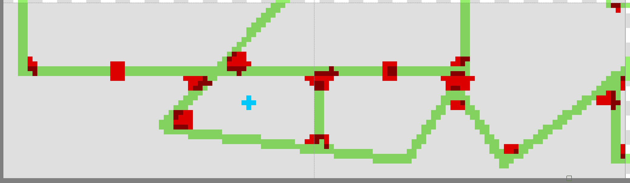
But going back to the distance maps, using my test image, I clicked somewhere around the blue cross and got this map for a 1px gap size. Again, this is based on actual data produced by MyPaint.

And this is with a 3px gap:

The image above is an 8-bit per channel “visualization”, so precision is lost here because the original map is 16-bit alpha. The values were in the 0-8192 range. The grid line is the 64x64 pixel tile marker, MyPaint is tiling the images like this probably because it has an infinite canvas.

Here’s an actual fill result for that click:

Here’s the close-up of that one corner with a rectangular distance map. Intensively red pixels are the shortest distance (1) and the faintest are the longest (9). Surrounding areas are value 8192 (“very far”).

I think the distance map can help with terminating the gap area in a neat way (more circular). All in all, MyPaint algorithm has a lot of nuance to it, which probably is necessary to get a better quality result in all the weird cases.

Hi all, it’s time for an update :slight_smile:

I’ll start with the specifics. I have a working implementation in the prototype app. I decided to just port the MyPaint code, with some adjustments, and hopefully, enhancements.

Here are some examples of the current behavior.

Low res image, 3px gap (comments below the video):

  • The first few seconds show the distance map. Red pixels are the distance to a gap, with high intensity red color meaning a short distance (close to the center of the gap). White areas are “very far”.
  • This version allows expanding the fill from inside a narrow area (inside the gap). This has a potential for some bad behavior, and it’s worked around by allowing some tolerance when comparing the distances.

At a very large gap size (compared to line thickness), the map becomes rather hard to read:

And filling some areas will result in unexpected gaps, or conversely, leaking through edges:

I don’t think these issues can be fully solved in a robust way. We will have to tune it, or possibly go with MyPaint’s original behavior, where the fill cannot expand into an open area if starting in a gap. With the drag-fill feature, it’s not too big of an issue, I think.

Here’s another example, with a high-resolution image (1429 x 2249 pixels). Gap size 15 px, tolerance 20% (when considering if a pixel is “empty” for the purpose of the fill):

(This video is stop motion, because the prototype is really slow when filling a large bitmap. It’s a simple C# WinForms app).


OK, so my next update here should be a working Krita implementation that could be tested more thoroughly in terms of quality and performance.

I don’t see any major obstacles at this point, everything should translate simply into C++. Likewise, I don’t think there will be any big paradigm issue with how Krita handles the fill itself or the selection masks. The main difficulty is that the distance (gap) map has to be precomputed before the fill, but it shouldn’t be that slow, and naturally it could be optimized in a few ways.

So stay tuned, and I hope I’ll be able to deliver something soon :slight_smile:

Sounds promising.
It would be great if you made a small document explaining the inner work of the algorithm. I’ll probably review the mr since I made the changes to the fill tool in the last years, and knowing how the algorithm works without having to look at the code would be useful. It can also make the porting smoother for you since some advice could be provided.

Sure, I will include it in the MR. I was thinking about just adding a doc (a markdown/asciidoc, etc.) to the sources directly.